
Category: Electricity
Specification: PS-E-13 (rev. 1)
Distribution Date: 2007-06-25
Effective Date: 2007-06-25
Supersedes: PS-E-13
Table of contents
- 1.0 Scope
- 2.0 Authority
- 3.0 References
- 4.0 Terminology
- 5.0 General requirements
- 6.0 Ratings
- 7.0 Electrical requirements
- 8.0 Marking requirements
- 9.0 Metrological requirements
- 10.0 Sealing requirements
- 11.0 Accuracy class limits of error
- 12.0 Revision
1.0 Scope
This specification applies to electronic current transformers which are intended to be used in revenue metering.
2.0 Authority
This specification is issued pursuant to subsection 12 (1) of the Electricity and Gas Inspection Regulations.
3.0 References
Electricity and Gas Inspection Act (R.S. 1985, c. E-4), ss. 9(4).
Electricity and Gas Inspection Regulations (SOR/86-13), ss. 12(1).
Measurement Canada, LMB-EG-07: Specifications for the Approval of Type of Electricity Meters, Instrument Transformers, and Auxiliary Devices.
International Electrotechnical Commission, 60044-8.
CAN-CSA 60044-1, Instrument Transformers Part 1: Current Transformers
CAN-CSA 60044-8, Instrument Transformers Part 8: Electronic Current Transformers
4.0 Terminology
The following terminology is in addition to definitions established in LMB-EG-07:
- Electronic Instrument Transformer (EIT)
-
An arrangement consisting of one or more current or voltage sensor(s) which may be connected to transmitting systems and secondary converters, all intended to transmit a measuring quantity in a proportional quantity to supply measuring instruments, metering devices.
- Electronic Current Transformer (ECT)
-
An EIT in which the secondary current in normal conditions of use is substantially proportional to the primary current and differs in phase from it by a known angle for an appropriate direction of the connections.
Note: The terms "measuring current transformer" and "metering current transformer" are equivalent.
5.0 General requirements
Electronic current transformers shall comply with all applicable requirements established in section 3 of LMB-EG-07 in addition to the requirements specified in this document.
6.0 Ratings
6.1 Rated primary current
Ratings shall be those established in section 14-3.4 of LMB-EG-07.
6.2 Rated secondary outputs
Analog output: The preferred value of rated secondary low output is 4 V for both phase-to-phase and phase-to-ground measurement systems. ECT having a high energy analog output with 5A or 1A output standard shall do so in accordance with tables A and table B.
Digital Output: The digital output of the ECT shall be in accordance to clause 5.3 of IEC 60044-8.
6.3 Rated burden
The value of rated burden is a resistive burden of 5kΩ in parallel with 5 nF for secondary output of 4 V. The value of rated burden in table A shall be applicable for secondary current of 5 A. For ECT having secondary output of 1 A, the burden specified in table B shall be applicable.
7.0 Electrical requirements
ECT shall meet the insulation requirements established in section 14-3.2.1 of LMB-EG-07. The rated insulation level of a primary winding of a current transformer shall be based on its highest voltage for equipment Um . For a current transformer without primary winding and without primary insulation of its own, the value Um = 0,72 kV is assumed.
ECT shall meet the requirements of clause 6.1.2 of IEC 60044-8 for limits of temperature rise.
8.0 Marking requirements
8.1 Terminals
The terminals shall be identified as established in section 14-3.3.1 of LMB-EG-07.
8.2 Relative polarities
All terminals marked H1, X1, Y1 shall have the same polarity at the same instant.
8.3 Nameplate
Nameplates shall include all applicable information as established in section 14-3.3.2 of LMB-EG-07. Nameplates shall be positioned as stated in section 14-3.3.2.1 of LMB-EG-07.
9.0 Metrological requirements
9.1 Basic accuracy
The ECT shall comply with the accuracy requirements established in Table C and Figure 1 for the accuracy class in which it is designated.
9.2 Accuracy versus temperature
The ECT shall comply with its accuracy designation in Table C and Figure 1 when tested according to clause 8.9.3 of IEC 60044-8.
9.3 Accuracy versus frequency
The ECT shall comply with its accuracy designation in Table C and Figure 1 when tested according to clause 8.9.4 of IEC 60044-8.
9.4 Accuracy versus auxiliary voltage variation
The ECT shall comply with its accuracy designation in Table C and Figure 1 when its auxiliary voltage is varied ±10% from the nominal AC auxiliary voltage; and when varied ±20% from the nominal DC auxiliary voltage.
10.0 Sealing requirements
10.1 Programming security
The basic operating/metering constants and the algorithm used in processing the measured quantities shall be stored within the ECT in such manner that they cannot be altered by any external device, communication signal, power outage or any other means which does not require breaking the device's physical seal (Clause 3.2.6 - LMB-EG-07).
11.0 Accuracy class limits of error
12.0 Revision
The purpose of revision 1 is to correct the information in Tables A & B of the original Provisional Specification that was effective 2006-02-06.
Figure 1–Limits for measuring current transformer
Limits of 0.15 accuracy class
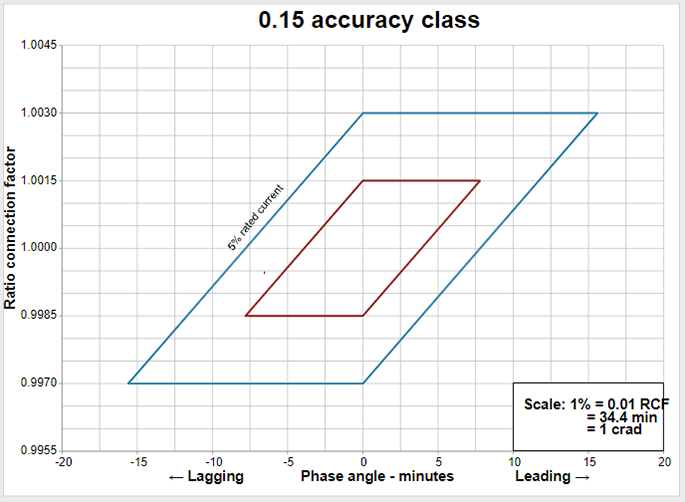
Description of limits of 0.15 accuracy class figure
The relationships between the limits of the ratio correction factors and the phase angle for the limiting values of the transformer correction factors (TCFs) specified in Table 3 are provided by parallelograms that are plotted on graphs in which a phase angle correction factor in minutes appears on the x-axis and a ratio correction factor appears on the y-axis. The parallelograms defining the limiting values of the TCFs for current transformers are bound by vertices. For a 0.15 accuracy class at a 5% rated current, the limiting values are (0, 1.003), (15.6, 1.003), (0, 0.997) and (-15.6, .997). At a 100% rated current, the limiting values are (0, 1.0015), (7.8, 1.0015), (0, 0.9985) and (-7.8, 0.9985).
Limits of 0.3 accuracy class
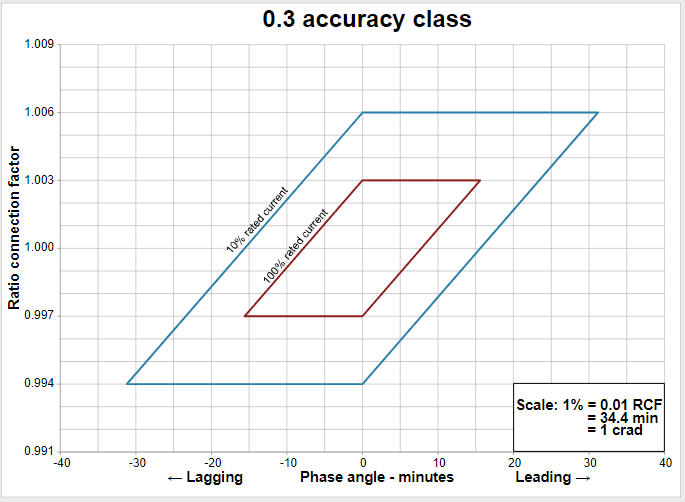
Description of imits of 0.3 accuracy class figure
The relationships between the limits of the ratio correction factors and the phase angle for the limiting values of the transformer correction factors (TCFs) specified in Table 3 are provided by parallelograms that are plotted on graphs in which a phase angle correction factor in minutes appears on the x-axis and a ratio correction factor appears on the y-axis. The parallelograms defining the limiting values of the TCFs for current transformers are bound by vertices. For a 0.3 accuracy class at a 10% rated current, the limiting values are (0, 1.006), (31.2, 1.006), (0, 0.994) and (-31.2, 0.994). At a 100% rated current, the limiting values are (0, 1.003), (15.6, 1.003), (0, 0.997) and (-15.6, 0.997).
Limits of 0.6 accuracy class
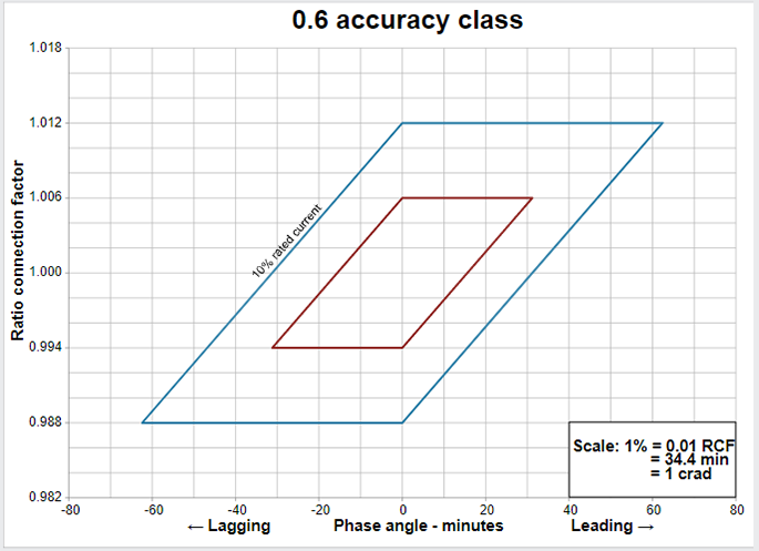
Description of limits of 0.6 accuracy class figure
The relationships between the limits of the ratio correction factors and the phase angle for the limiting values of the transformer correction factors (TCFs) specified in Table 3 are provided by parallelograms that are plotted on graphs in which a phase angle correction factor in minutes appears on the x-axis and a ratio correction factor appears on the y-axis. The parallelograms defining the limiting values of the TCFs for current transformers are bound by vertices. For a 0.6 accuracy class at a 10% rated current, the limiting values are (0, 1.012), (62.4, 1.012), (0, 0.988) and (62.4, 0.988). At a 100% rated current, the limiting values are (0, 1.006), (31.2, 1.006), (0, 0.994) and (31.2, 0.994)